
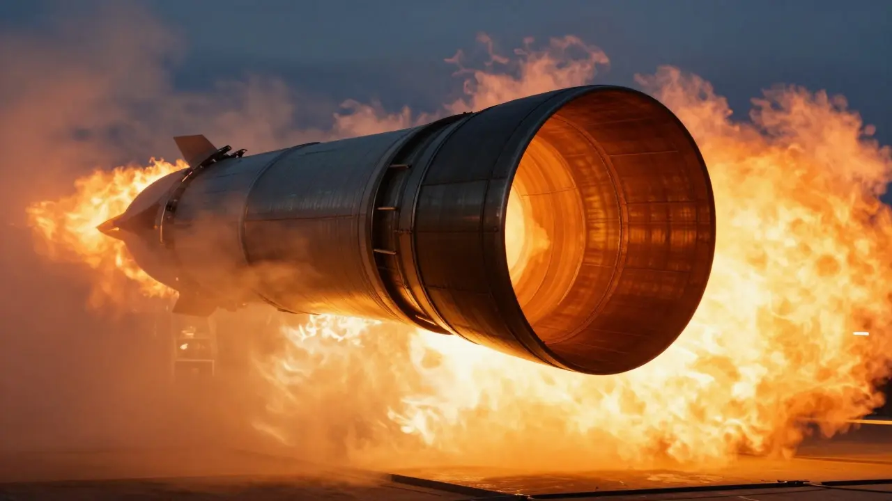
Imagine you are holding a garden hose. If you put your thumb over the end, the water shoots out faster and with more force. Now imagine that hose is expanding into a massive bell shape. In rocket propulsion, this shape is called the nozzle, and its geometry determines how much of the hot gas energy turns into useful thrust. The specific number that defines this shape is the nozzle expansion ratio, which is simply the area of the exit opening divided by the area of the narrowest point (the throat). This single geometric parameter dictates whether an engine performs well at liftoff or in the void of space.
The Core Physics: Why the Ratio Matters
To understand why we care about this number, you have to look at what happens to the gas inside the engine. When propellant burns in the combustion chamber, it creates high-pressure gas. As this gas flows through the nozzle, it accelerates. According to thermodynamic principles, for a fixed chamber pressure and propellant mix, the expansion ratio uniquely determines the exit Mach number, exit pressure, and velocity.
Here is the critical trade-off: if the exit pressure matches the ambient air pressure outside, the engine is operating at "ideal" efficiency. If the exit pressure is higher than the ambient pressure, the gas is "underexpanded"-it has leftover energy that isn't being converted into thrust. If the exit pressure is lower than the ambient pressure, the gas is "overexpanded." While underexpansion just wastes potential performance, overexpansion can be catastrophic because the external air pressure pushes back against the exhaust jet, potentially causing the airflow to separate from the nozzle walls.
Sea-Level Engines: The Compromise of Density
First-stage boosters operate in a hostile environment. At liftoff, the ambient pressure is roughly 101 kPa (1 atmosphere). If you use a highly expanded nozzle designed for vacuum here, the exit pressure will drop significantly below the surrounding air pressure. This adverse pressure gradient causes the boundary layer of the exhaust flow to separate from the nozzle wall.
Flow separation is not just a theoretical inconvenience; it creates asymmetric side loads that can shake the engine or even break structural components. To avoid this, sea-level engines use modest expansion ratios. Typical values range from 8:1 to 35:1. Designers deliberately keep these nozzles "underexpanded" at liftoff. They accept the loss of some specific impulse (efficiency) in exchange for stable, attached flow and manageable structural loads.
For example, the SpaceX Merlin 1D engine used on Falcon 9 has an expansion ratio of approximately 16:1. This allows it to produce reliable thrust at sea level without suffering from severe flow separation. As the rocket climbs and the ambient pressure drops, this same nozzle becomes less inefficient, but it never reaches its full vacuum potential. That is the price paid for robustness at launch.
Vacuum Engines: Chasing Maximum Efficiency
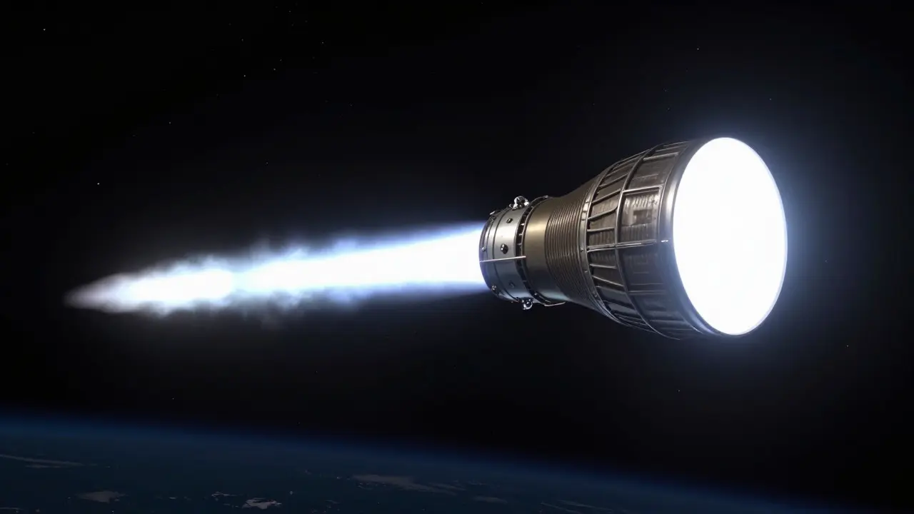
Upper-stage engines ignite once the vehicle is above most of the atmosphere, where ambient pressure is effectively zero. In this environment, the fear of overexpansion and flow separation vanishes. Consequently, designers can stretch the nozzle to extreme lengths and large diameters to maximize the acceleration of the exhaust gases.
Vacuum-optimized engines typically use expansion ratios between 40:1 and 300:1. Deep-space engines, such as later variants of the RL10, exceed 280:1. By increasing the expansion ratio, the exit velocity increases, which directly boosts specific impulse. The Merlin 1D Vacuum variant, for instance, uses an expansion ratio of about 165:1. Compared to its sea-level counterpart, this yields a specific impulse of approximately 311 seconds versus 282 seconds-a significant 10.3% improvement in fuel efficiency for the same amount of propellant.
This gain comes with physical costs. A larger expansion ratio means a longer, thinner nozzle. This adds mass and complexity to the engine structure. On a first stage, where every kilogram of dead weight hurts payload capacity, this trade-off is rarely worth it. But on an upper stage, where the primary goal is maximizing delta-v (velocity change), the extra length is a worthwhile investment.
| Feature | Sea-Level Booster | Vacuum Upper Stage |
|---|---|---|
| Typical Expansion Ratio | 8:1 - 35:1 | 40:1 - 300:1 |
| Primary Constraint | Flow Separation / Structural Loads | Nozzle Mass / Length / Cooling |
| Exit Pressure at Design Point | Higher than Ambient (Underexpanded) | Close to Zero (Ideal/Vacuum) |
| Example Engine | SpaceX Merlin 1D (~16:1) | SpaceX Merlin 1D Vac (~165:1) |
| Specific Impulse Trend | Lowers as altitude increases (relative to ideal) | Increases monotonically with ratio |
The Altitude Dilemma and Flow Separation
You might wonder: why not just build one engine that works perfectly at all altitudes? The problem is that the "optimal" expansion ratio changes continuously as the rocket climbs. At sea level, you want a low ratio. At 100 km, you want a very high ratio. A fixed-geometry bell nozzle must compromise.
Engineers quantify this compromise using the concept of "performance loss due to ambient pressure." NASA studies have shown that a nozzle with a low area ratio (e.g., 5.49:1) gains only about 9.2% in specific impulse when moving from sea level to vacuum. In contrast, a highly expanded nozzle (e.g., 48.59:1) gains nearly 60%. This demonstrates that while high-expansion nozzles suffer huge penalties at low altitude, they reward the designer disproportionately in space.
However, pushing the expansion ratio too high for a sea-level application risks hitting the separation limit. Practitioners often use a rule of thumb: keep the exit pressure at liftoff no lower than 40-50% of the ambient pressure. If you go lower than that, the risk of unsteady separation spikes. This constraint forces first-stage designers to stay within the 10:1 to 30:1 range, regardless of how much more efficient a 50:1 nozzle would theoretically be at mid-altitudes.
Advanced Concepts: Breaking the Fixed Geometry Limit
Because fixed nozzles are inherently compromised, researchers have developed altitude-compensating nozzle concepts. These designs aim to mimic the behavior of an ideal nozzle that adjusts its shape in real-time to match the changing ambient pressure.
- Aerospike Engines: These use a central spike to expand the exhaust plume. The ambient air pressure helps shape the flow, allowing the engine to remain efficient across a wide range of altitudes without massive geometric changes.
- Dual-Bell Nozzles: These feature two concentric nozzles. One is optimized for sea-level operation, and the other for vacuum. Depending on the altitude, the flow naturally switches to the appropriate path, reducing the penalty of a single fixed ratio.
- Expansion-Deflection (ED) Nozzles: These use movable surfaces to adjust the effective expansion ratio dynamically. CFD simulations show that ED nozzles can maintain higher efficiency across various pressure ratios compared to simple bell nozzles.
While these technologies offer superior theoretical performance, they introduce complexity, weight, and control challenges. For now, the industry standard remains the fixed bell nozzle, carefully tuned either for sea-level robustness or vacuum efficiency depending on the mission phase.
Practical Design Guidelines and Trade-offs
If you are involved in rocketry, whether professionally or as an advanced amateur, selecting the right expansion ratio involves balancing several factors beyond just thermodynamics.
- Chamber Pressure: Higher chamber pressures allow for higher expansion ratios before separation occurs. A modern high-pressure engine can tolerate a larger nozzle than a low-pressure engine of the same size.
- Trajectory Profile: A booster that flies straight up may handle slightly different side loads than one that pitches downrange early. The allowable expansion ratio depends on the maximum side load expected during flight.
- Structural Mass: Every centimeter of added nozzle length adds weight. In vacuum, this weight must be justified by the delta-v gained. In sea-level applications, the weight penalty often outweighs the marginal efficiency gains of a slightly larger nozzle.
- Cooling Complexity: Larger nozzles require more cooling channels. Additive manufacturing has helped mitigate this, but heat flux management remains a critical design constraint for high-expansion ratios.
Recent studies, including those analyzing the J-2X nozzle extension, show that doubling the area ratio from 27.5:1 to 55:1 significantly boosts vacuum performance. However, this also increased the nozzle length, complicating structural support. There is no single "correct" number; rather, the optimal ratio is a function of the specific mission profile, vehicle architecture, and available technology.
Frequently Asked Questions
What is the ideal expansion ratio for a sea-level rocket engine?
There is no single ideal number, but typical sea-level booster engines use expansion ratios between 8:1 and 35:1. The specific choice depends on the chamber pressure and the need to avoid flow separation at liftoff. Designers usually aim for an exit pressure that is roughly 40-50% of the ambient pressure to ensure stable flow.
Why do vacuum engines have such long nozzles?
Long nozzles allow for a higher expansion ratio, which accelerates the exhaust gases to higher velocities. Since there is no atmospheric pressure to cause flow separation in vacuum, engineers can extend the nozzle to maximize specific impulse. This results in better fuel efficiency for upper stages and deep-space missions.
What happens if a sea-level engine uses a vacuum-optimized nozzle?
The engine would likely suffer from severe flow separation. The exit pressure would drop far below the ambient air pressure, causing the exhaust jet to detach from the nozzle walls. This creates unstable side loads that can damage the engine or destabilize the rocket, and it results in lower thrust than a properly sized sea-level nozzle.
How does chamber pressure affect the choice of expansion ratio?
Higher chamber pressure allows for a higher expansion ratio before flow separation occurs. Because the pressure difference between the exhaust and the ambient air is larger, the flow remains attached to the nozzle walls for a longer distance. This is why modern high-pressure engines can utilize more aggressive nozzle geometries than older low-pressure designs.
Can a single engine work efficiently at both sea level and vacuum?
A standard fixed-bell nozzle cannot be optimal for both. It must compromise, resulting in underexpansion at sea level or overexpansion issues. However, altitude-compensating nozzles like aerospike or dual-bell designs can approximate optimal performance across a wider range of altitudes, though they add complexity and weight.