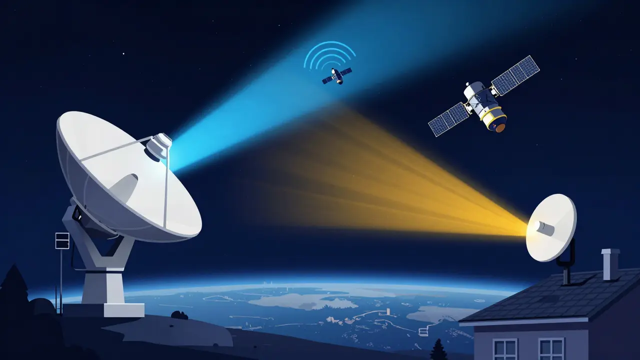
Ever wondered how your laptop talks to a metal box orbiting 500 kilometers above the Earth? It’s not magic, but it is a carefully choreographed dance of radio waves. This two-way street is called bidirectional satellite communication, and it relies on two distinct paths: the uplink and the downlink. Without this precise pairing, everything from live sports broadcasts to rural broadband internet would grind to a halt.
In 2026, this technology isn’t just for government agencies anymore. With the global satellite internet market projected to hit USD 16.81 billion this year, millions of users rely on these links daily. Whether you are streaming video in a remote cabin or connecting a shipping container across the ocean, understanding how these signals travel helps explain why your connection sometimes drops during a rainstorm and why new satellites feel so much faster than the old ones.
The Basic Anatomy of a Signal Path
To understand satellite communication, you first need to separate the journey into two halves. Think of it like a phone call, but with extreme distance involved.
Uplink is the transmission path from a ground station, user terminal, or gateway toward a satellite. In simple terms, this is your device sending data *up* to space. When you click “send” on an email or upload a photo, that data travels via the uplink.
Downlink is the path from the satellite toward one or more ground receivers. This is the return trip. The satellite receives your request, processes it (or beams it to another ground station), and sends the response back *down* to your antenna. Loading a webpage or watching a movie happens over the downlink.
These aren't just arbitrary labels; they are standardized terms used by engineers worldwide. The distinction matters because the physics governing each direction are different. The uplink fights gravity and atmospheric density from the bottom up, while the downlink deals with signal degradation over long distances before hitting your receiver.
Why Frequency Matters: Uplink vs. Downlink Bands
You might think both directions use the same frequency, but they don’t. If they did, the powerful signal going up would drown out the weak signal coming down. To prevent this interference, regulators assign different frequency bands for each direction.
A key rule of thumb in satellite engineering is that uplink transmissions typically operate at higher frequencies than downlink transmissions. Why? Because lower frequencies penetrate the atmosphere better. By assigning the lower band to the downlink, engineers ensure that the signal reaching your home antenna suffers less attenuation (weakening) from rain and clouds.
| Band | Uplink Range (GHz) | Downlink Range (GHz) | Primary Use Case |
|---|---|---|---|
| C-Band | 5.925 - 6.425 | 3.7 - 4.2 | Highly reliable broadcast TV; resistant to rain fade |
| Ku-Band | 13.75 - 14.5 | 10.7 - 12.75 | Direct-to-home TV; standard consumer satellite internet |
| Ka-Band | 27.5 - 31.0 | 17.7 - 21.2 | High-throughput LEO internet (e.g., Starlink); high speed, weather-sensitive |
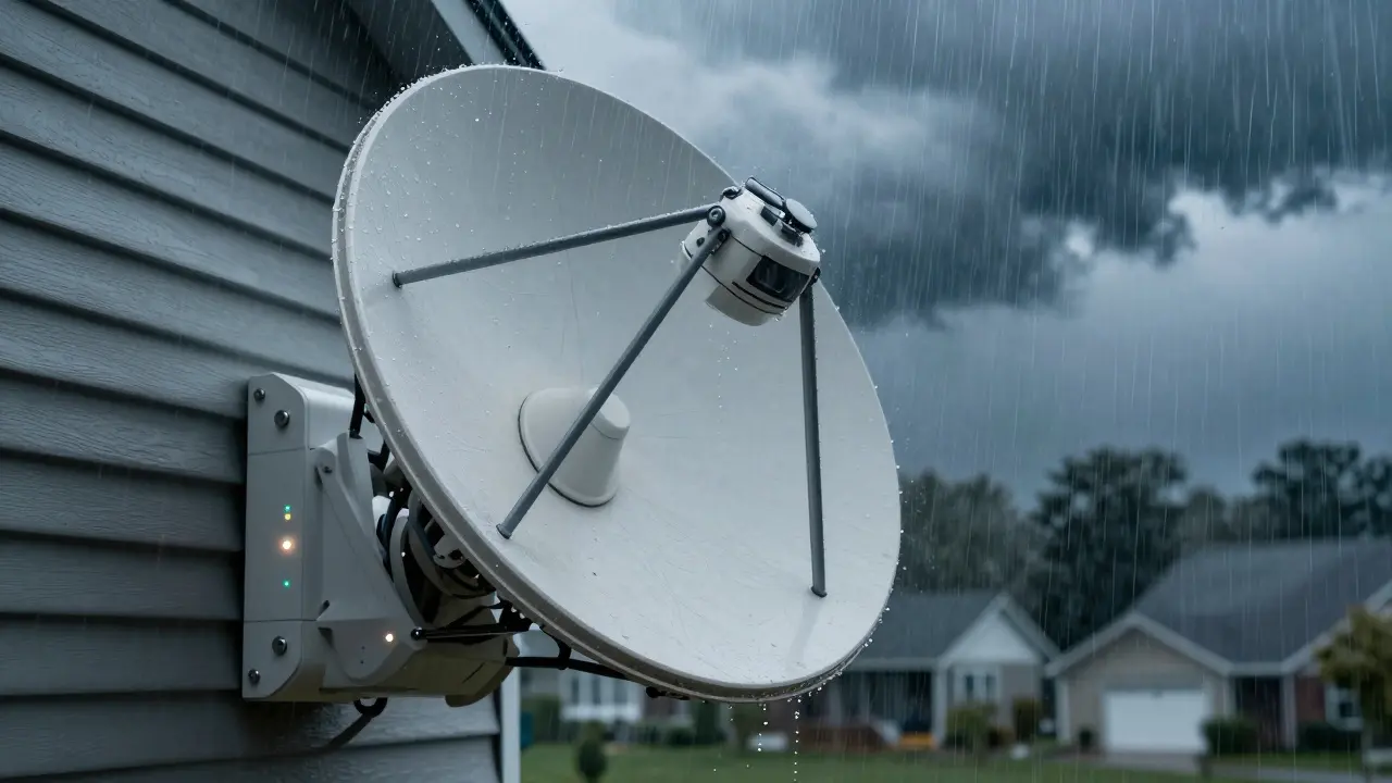
Notice the pattern? C-band uses the lowest frequencies, making it incredibly robust against bad weather. That’s why critical infrastructure often sticks to C-band. On the other end, Ka-band uses much higher frequencies. This allows for wider bandwidths and faster speeds, which is essential for modern broadband, but it comes with a trade-off: heavy rain can block the signal entirely. This phenomenon, known as rain fade, is why your satellite internet might stutter during a thunderstorm.
The Shift to Low Earth Orbit (LEO)
For decades, most satellites sat in Geostationary Earth Orbit (GEO), hovering about 35,786 km above the equator. While stable, this distance creates a significant problem: latency. A signal has to travel nearly 72,000 km round-trip, resulting in delays of 600-700 milliseconds. Try playing an online game or having a real-time video call with that lag, and you’ll quickly notice the disconnect.
This is where Low Earth Orbit (LEO) constellations change the game. Satellites like those in SpaceX’s Starlink or Amazon’s Kuiper network orbit between 500 and 1,200 km above Earth. This proximity slashes the round-trip latency to tens of milliseconds-comparable to terrestrial fiber optics in many cases.
However, moving closer to Earth introduces new challenges. Because LEO satellites move rapidly relative to the ground (orbiting every 90 minutes or so), your antenna can’t just point at one spot and stay there. Modern user terminals use electronically steered phased-array antennas. These devices contain dozens or hundreds of tiny radio elements that beamform signals dynamically, tracking multiple satellites simultaneously without any moving parts. This hardware handles both the uplink and downlink seamlessly, switching beams as satellites rise and set.
Link Budget: The Math Behind the Magic
If you want to know if a satellite link will actually work, you don’t guess-you calculate the Link Budget. This is a detailed accounting of all the gains and losses a signal experiences from transmitter to receiver.
Engineers must calculate this separately for the uplink and the downlink because the conditions differ drastically. Key factors include:
- EIRP (Effective Isotropic Radiated Power): How strong the signal leaves the antenna.
- Free-Space Path Loss: Signal weakening due to distance.
- Atmospheric Absorption: Losses caused by oxygen, water vapor, and rain.
- Antenna Gain: How well the dish focuses the signal.
- Noise Figure: Background static that interferes with reception.
The goal is to ensure the received power exceeds the receiver’s sensitivity threshold by a comfortable margin-typically 3 to 6 decibels (dB). This margin accounts for unexpected variables like hardware aging, slight pointing errors, or sudden storms. If your calculated Signal-to-Noise Ratio (SNR) falls below the minimum required for your modulation scheme (like 64-QAM), the link fails. No amount of transmit power can fix a broken link budget if the noise floor is too high or the losses are underestimated.
Tools like MathWorks’ satellite communications toolbox allow engineers to simulate these scenarios, adjusting variables like orbit altitude and wavelength to predict performance before building expensive hardware. Ignoring implementation losses or underestimating rain fade is a common beginner mistake that leads to intermittent outages in real-world deployments.
Future Trends: Optical Feeder Links
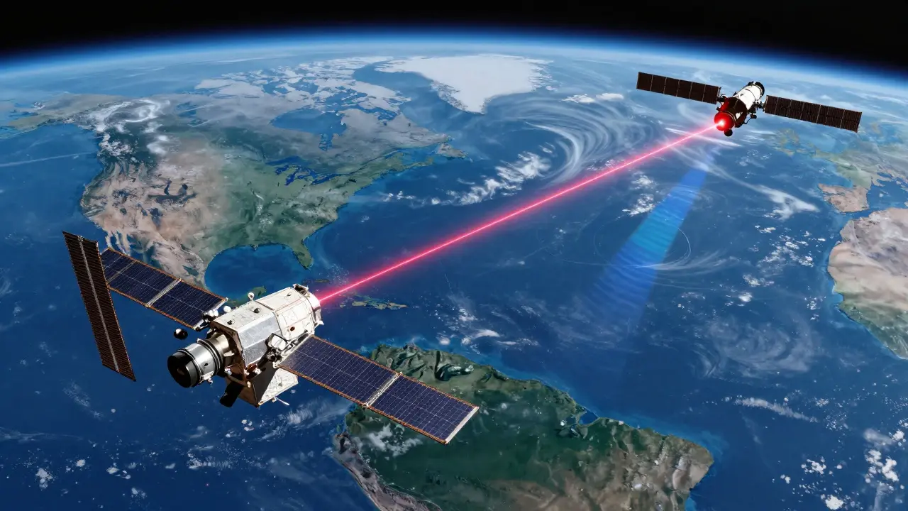
As demand for bandwidth explodes, traditional radio frequency (RF) links are hitting capacity limits. The next frontier is optical communication. Imagine replacing radio waves with lasers for the backbone of the satellite network.
Recent studies, including research published in Nature Scientific Reports, have demonstrated bi-directional optical feeder links between LEO and GEO satellites. In this hybrid architecture, high-capacity laser beams carry aggregated data between satellites and gateways, while RF uplinks and downlinks continue to serve end-user terminals. This approach combines the massive throughput of optical links with the mature, weather-resilient ecosystem of RF user equipment.
Optical links offer multi-gigabit speeds but require extreme precision. Pointing a laser at a moving satellite from thousands of kilometers away demands advanced stabilization systems to combat turbulence and cloud cover. While still emerging, this technology promises to relieve congestion in crowded RF spectrum bands, ensuring that bidirectional satellite communication can scale to meet the needs of tens of millions of future users.
Practical Implications for Users and Engineers
For the average consumer, understanding uplinks and downlinks means knowing what to expect from your service. If you live in an area with frequent heavy rain, Ka-band services may require adaptive coding and modulation to maintain connectivity, potentially slowing speeds during storms. For enterprise users, prioritizing uplink-heavy traffic (like SCADA telemetry) requires specific plan configurations, as most consumer plans are optimized for downlink-heavy activities like video streaming.
For engineers designing these systems, the takeaway is clear: never treat the uplink and downlink as symmetric problems. They have different regulatory constraints, different atmospheric interactions, and different hardware requirements. Successful design involves iterative testing, realistic margin calculations, and a deep respect for the physical limitations of the environment.
What is the main difference between uplink and downlink?
The uplink is the signal path from Earth to the satellite, carrying commands and user data upward. The downlink is the path from the satellite back to Earth, delivering content and responses to receivers. They use different frequencies to avoid interference.
Why does rain affect satellite internet more than cable?
Satellite signals travel through the atmosphere, where water droplets absorb and scatter radio waves, especially at higher frequencies like Ka-band. This is called rain fade. Cable signals travel through underground fibers, which are shielded from weather conditions.
How do LEO satellites reduce latency compared to GEO?
LEO satellites orbit much closer to Earth (500-1,200 km) than GEO satellites (35,786 km). The shorter distance means signals take significantly less time to travel up and down, reducing round-trip latency from ~600ms to under 100ms.
What is a link budget in satellite communication?
A link budget is a calculation that sums all the gains (like antenna focus) and losses (like distance and atmospheric absorption) in a communication path. It ensures the received signal is strong enough to be decoded correctly.
Will optical satellite links replace radio frequencies?
Not entirely. Optical links are likely to be used for high-capacity feeder links between satellites and ground stations. However, RF will remain dominant for last-mile connections to user terminals because it penetrates clouds and rain better than lasers.