
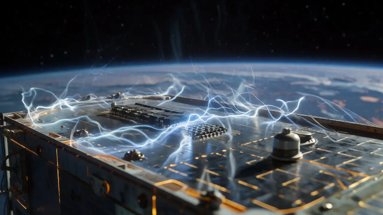
Imagine a satellite drifting through the vacuum of Low Earth Orbit. It’s not just floating in empty space; it’s swimming in a soup of charged particles called plasma. If your Space Electrical Power System isn’t designed with extreme care, that invisible soup can build up static charge on the spacecraft’s surface until-snap-an arc jumps across a circuit board, frying the mission. This isn’t hypothetical. In the early days of spaceflight, uncontrolled charging caused mysterious glitches and even lost satellites. Today, strict safety standards govern every volt and ampere flowing through our orbiting hardware.
Designing power systems for space is fundamentally different from wiring a house or a factory. On Earth, air helps dissipate heat and prevents arcing. In space, you have no air, intense radiation, and extreme temperature swings. The stakes are higher because there’s no one coming to fix a shorted wire. You need to know which standards apply, how to prevent arcs, and how to keep astronauts safe during spacewalks. Let’s break down the regulatory landscape and technical realities that keep our power grids in orbit running safely.
The Core Safety Hazards: Why Space Power Is Different
Before diving into the rulebooks, you need to understand what we’re trying to stop. Three main threats dominate the design phase: spacecraft charging, radiation-induced faults, and debris impacts.
Spacecraft Charging is the silent killer. As a spacecraft moves through plasma, electrons and ions hit its surfaces at different rates. Insulating materials like solar array covers or cable jackets can trap this charge, creating high voltage potentials relative to the surrounding plasma. If the potential difference gets too high, electricity arcs to another part of the ship or to ground. This is governed by NASA-STD-4005A, which specifically targets spacecraft operating above 55 Volts in Low Earth Orbit (LEO). If you’re building a geostationary satellite, this standard doesn’t fully apply, but you still face charging risks from auroral electrons.
Radiation Effects pose a direct threat to power electronics. High-energy particles can trigger Single Event Latchup (SEL) or Single Event Burnout (SEB) in components like MOSFETs and thyristors. An SEL can turn a switch permanently "on," causing massive current draw and overheating. SEB can destroy the component entirely. These aren't rare anomalies; they are expected events that must be mitigated through shielding and fault-tolerant design.
Debris and Micrometeoroids add physical risk. With over 12,000 tracked objects larger than 10 cm traveling at speeds between 8 km/s and 70 km/s, a small impact can sever a power harness. Unlike on Earth, you can’t just patch a hole. Redundancy and shielding are your only defenses.
NASA Standards: The American Framework
If you’re working with NASA or on a US-led mission, your bible is likely NASA-STD-4005A. Approved in 2016 and revalidated in 2021, this standard dictates how to handle high-voltage systems in LEO. It applies to altitudes up to 2,000 km and latitudes between -50° and +50°. Its primary goal? Prevent differential charging that leads to arcing.
But flight hardware isn’t the only concern. Ground support equipment and test facilities must adhere to terrestrial safety codes. NPR 8715.3C mandates that all NASA electrical work follows NFPA 70 (the National Electrical Code) and NFPA 70E (Electrical Safety in the Workplace). This means if you’re testing a high-voltage battery pack on the ground, you need certified personnel, proper lockout/tagout procedures, and grounded enclosures for anything above 600 V.
For the International Space Station (ISS), specific interface requirements exist. Documents like SSP 30243 control Electromagnetic Compatibility (EMC), ensuring your payload doesn’t interfere with other station systems. Meanwhile, SSP 30245 handles bonding, tailored from military spec MIL-B-5087B, to ensure all metal parts share the same electrical reference point. Failure here creates ground loops, which can corrupt data signals or create shock hazards.
ECSS Standards: The European Approach
Europe operates under the European Cooperation for Space Standardization (ECSS). While similar in spirit to NASA’s rules, ECSS tends to be more prescriptive about component-level details. If you’re designing for ESA missions, you’ll encounter three critical documents:
- ECSS-E-ST-20-06C Rev.1: Covers spacecraft charging. Like NASA’s standard, it sets limits on surface potentials and requires conductive coatings or grounding schemes to mitigate buildup.
- ECSS-E-ST-20-08C Rev.2: Focuses on photovoltaic assemblies. It details qualification tests for solar cells against radiation, mechanical launch loads, and electrical isolation distances. The latest revision, dated April 2023, reflects modern high-efficiency cell technologies.
- ECSS-E-ST-20-20C: Defines electrical design and interface requirements for power supplies. It specifies bus voltage ranges, ripple limits, and transient response times, ensuring compatibility between different contractors’ hardware.
European missions also rely heavily on formal nonconformance control. ECSS-Q-ST-10-09C outlines exactly how to record, analyze, and dispose of deviations. If a solar panel string fails a test, you don’t just swap it out; you document why, assess the risk, and get approval before proceeding. This rigor ensures that lessons learned are captured and applied.
Critical Design Choices: Voltage, Protection, and Grounding
Choosing your bus voltage is a trade-off game. Higher voltages reduce current, which allows for thinner, lighter cables-a huge win when every gram costs thousands of dollars to launch. However, higher voltage increases the risk of insulation breakdown in vacuum. You need thicker creepage distances (the shortest path along the surface of an insulator) and clearance distances (the shortest path through air/vacuum). NASA-STD-4005A provides the thresholds for when these risks become unacceptable.
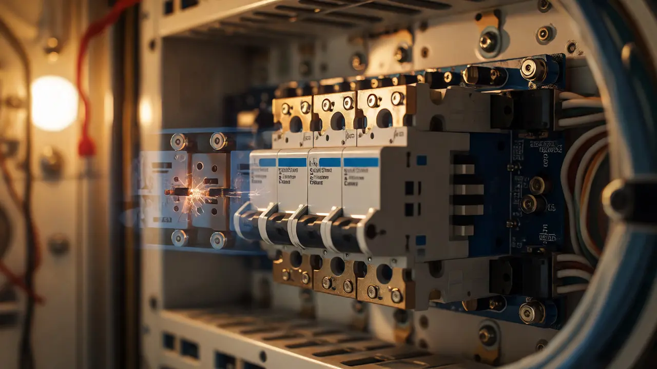
Then there’s fault protection. Mechanical circuit breakers, common on Earth, are problematic in space. They take milliseconds to trip, which is an eternity in electronics. In an oxygen-rich cabin like the ISS, a sustained arc can ignite fires. Solid-state circuit breakers (SSCBs) respond in microseconds (1-100 µs). They eliminate the physical contact points that cause arcs, making them far safer for crewed missions and sensitive payloads.
| Feature | Mechanical Breaker | Solid-State Circuit Breaker (SSCB) |
|---|---|---|
| Response Time | Tens of milliseconds | 1-100 microseconds |
| Arc Risk | High (especially in O2 environments) | Negligible |
| Lifespan | Limited by contact wear | Unlimited (no moving parts) |
| Complexity | Low | Higher (requires control logic) |
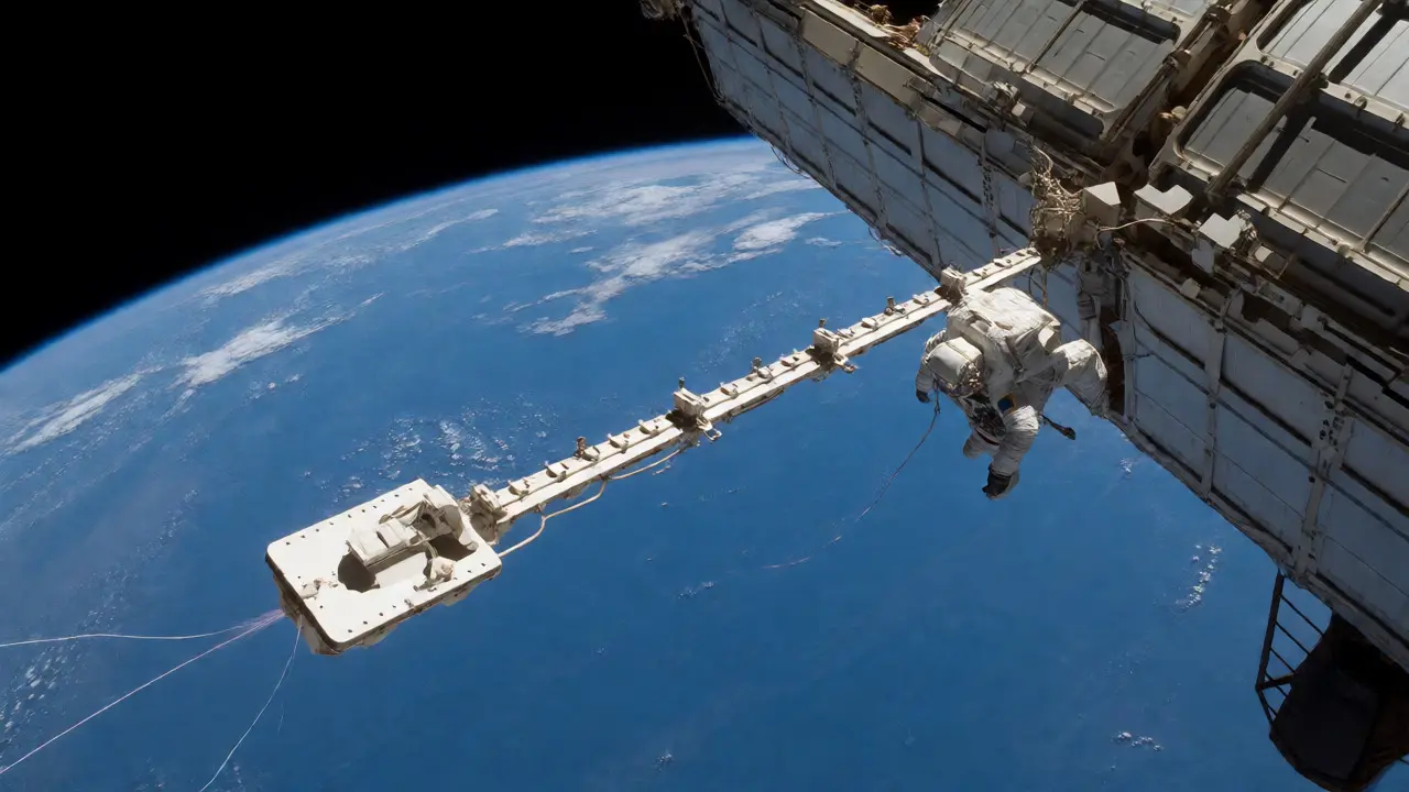
Grounding strategy is equally vital. On the ISS, the negative side of the power system is grounded to the structure. This can store energy at approximately -140 V relative to ambient plasma. Without active management, this charge could arc to a spacewalking astronaut. To solve this, the ISS uses Plasma Contactor Units (PCUs). These devices emit low-energy electrons into the plasma, effectively acting as a "ground wire" to neutralize the station’s charge. This innovation turned a major hazard into a manageable operational procedure.
Radiation Hardening and Fault Tolerance
You can’t shield everything. Adding lead or heavy metals to block radiation adds mass, which defeats the purpose of efficient power distribution. Instead, engineers use smart architecture. Triple Modular Redundancy (TMR) is a common technique where three identical circuits perform the same calculation. If one gets flipped by a cosmic ray, the other two outvote it. This is crucial for digital control logic managing power switching.
For analog components like MOSFETs, designers rely on encapsulation within grounded structures and specialized filters to suppress noise. Twisted-pair cabling helps reject electromagnetic interference (EMI). The recent push for fault-tolerant computing, such as NASA’s High Performance Spaceflight Computer (HPSC) initiative launched in 2024, shows that software-based error detection and correction are becoming as important as hardware shielding.
Future Trends: Radiation-Tolerant Solar Cells
The industry is evolving. In September 2026, the U.S. Department of Energy issued a call for research into space solar cell manufacturing, emphasizing mass, radiation tolerance, and durability. This signals a shift toward next-generation photovoltaics that degrade slower in harsh environments. As cells become more efficient and lighter, the standards governing their integration will tighten. We’re already seeing updates to ECSS-E-ST-20-08C to accommodate new module technologies.
Expect future standards to address cybersecurity in power management. As power systems become more software-defined, the ability to remotely reconfigure buses or reset breakers introduces new failure modes that traditional hardware-focused standards didn’t anticipate.
Why does NASA-STD-4005A exclude Geostationary Orbit?
NASA-STD-4005A focuses on Low Earth Orbit (LEO) plasma environments. GEO satellites operate in a different plasma regime with distinct charging mechanisms, primarily driven by electron flux rather than the mixed ion-electron environment of LEO. Therefore, GEO missions require separate analyses or additional guidelines beyond this specific standard.
What is the difference between creepage and clearance in space insulation?
Clearance is the shortest distance through the vacuum between two conductive parts. Creepage is the shortest distance along the surface of an insulating material. In vacuum, surface flashover (arcing along the surface) is often easier than breaking through the bulk material, so creepage distances are frequently the limiting factor in high-voltage space designs.
How do Plasma Contactor Units protect astronauts?
Large spacecraft like the ISS can accumulate significant electrical charge relative to the surrounding plasma. During spacewalks, an astronaut floating freely could experience a dangerous arc if they touch a highly charged structure. PCUs emit electrons to neutralize the spacecraft's potential, effectively grounding it to the plasma and preventing these arcs.
Are solid-state circuit breakers mandatory for all space missions?
Not always, but they are strongly preferred for crewed missions and high-reliability applications due to their microsecond response time and lack of arcing. Uncrewed, lower-risk missions might still use mechanical relays or fuses if weight and cost constraints outweigh the benefits of SSCBs, provided the environment doesn't pose an ignition risk.
Do ECSS and NASA standards conflict?
They generally align on core safety principles but differ in structure and specificity. NASA standards often integrate broader programmatic and occupational safety requirements (like NFPA codes), while ECSS standards tend to be more detailed regarding component-level engineering interfaces. Joint missions usually require harmonizing both sets of requirements.
11 Responses
The reliance on NASA-STD-4005A is a calculated obfuscation of the true risks inherent in plasma interaction.
One must consider that the standard's limitation to Low Earth Orbit serves primarily to exclude the more complex and less understood charging mechanisms found in Geostationary regimes, thereby reducing the regulatory burden on contractors.
It is highly probable that the 'soup' of charged particles described is merely a euphemism for uncontrolled electromagnetic interference which has plagued American space programs since the inception of the Apollo era.
The emphasis on solid-state circuit breakers appears to be driven less by safety necessity and more by the desire to eliminate mechanical failure points that would expose the fragility of our current engineering paradigms.
We are being told that redundancy solves all issues, yet history suggests that triple modular redundancy often fails simultaneously under specific radiation events that standards committees conveniently ignore.
The Plasma Contactor Units are not solutions but rather bandages applied to a systemic design flaw regarding grounding strategies in vacuum environments.
If one reads between the lines of the ECSS comparisons, it becomes evident that European standards are superior because they acknowledge component-level failures that NASA glosses over with broader programmatic requirements.
The mention of debris impacts at 8 km/s is trivialized; the kinetic energy involved renders shielding largely ineffective against larger tracked objects, suggesting a false sense of security.
Radiation hardening through TMR is an outdated concept when modern software-defined power management introduces cybersecurity vectors that traditional hardware-focused standards did not anticipate.
Therefore, the entire framework presented here is a construct designed to reassure investors rather than protect actual mission integrity against the chaotic nature of space plasma.
This breakdown is absolutely stellar! 🌟 It really helps demystify the invisible dangers lurking in orbit. I love how you highlighted the difference between creepage and clearance-it’s such a nuanced point that often gets overlooked in general discussions.
For anyone feeling overwhelmed by the acronyms like SEL or SEB, just think of them as cosmic hiccups that engineers have learned to catch before they become disasters.
The evolution from mechanical to solid-state breakers is truly inspiring progress. It shows how we’re adapting our tools to respect the harsh environment rather than fighting it blindly.
I’m particularly moved by the story of the Plasma Contactor Units turning a hazard into a manageable procedure. That’s ingenuity at its finest!
Keep shining light on these technical marvels, Hemali here cheering you on! 🚀✨
Moral imperative demands strict adherence. Safety isn't optional. It is right.
Standards exist to protect life. Ignoring them is wrong. We must do better.
Redundancy saves souls. Cutting corners kills. Simple truth.
Absolutely!!! This is exactly what happens when AMERICAN ENGINEERING LEADS THE WAY!!!
NASA-STD-4005A is the gold standard, period!!! No other country comes close to this level of rigor!!!
While Europe plays around with their prescriptive ECSS rules, we are out here solving problems with pure innovation!!!
Solid-State Circuit Breakers? Invented and perfected HERE!!!
The fact that they even mention ISS bonding specs proves how far ahead we are!!!
Let the others copy us!!! They always do!!!
This article is a testament to US dominance in space tech!!!
Don't let anyone tell you otherwise!!!
USA!!! USA!!! USA!!!
Thank you for sharing this. It helps me understand the global effort behind keeping astronauts safe. The collaboration between different standards feels important for future missions.
Great overview! 👩🔬 Just a small note: while SSCBs are preferred, don't forget that some legacy systems still use mechanical relays successfully if properly derated.
Also, the creepage distance issue is huge in vacuum because there's no air to cool the arc path, so surface tracking can happen way faster than people expect.
Make sure your insulation materials are outgassed properly too! 🧪 Otherwise, you get contamination on those high-voltage surfaces.
Happy designing! 🛠️📐
Your assertion regarding the superiority of American engineering ignores the historical context of international cooperation.
The claim that NASA leads the way disregards the fact that many foundational concepts in spacecraft charging were derived from Soviet-era research which was subsequently integrated into Western standards.
To suggest that Solid-State Circuit Breakers were invented exclusively in the United States is historically inaccurate given the global nature of semiconductor development.
Furthermore, the dismissal of ECSS standards as mere copying overlooks the rigorous nonconformance control processes outlined in ECSS-Q-ST-10-09C which provide deeper insight into failure analysis.
True leadership involves acknowledging shared knowledge bases rather than engaging in nationalist revisionism.
Love the energy here but lets keep it real about the voltage trade offs
Higher voltage is great for weight savings but you gotta watch those insulation limits super closely
Its a balancing act every single time
But hey thats why we engineer things right
Go team!
Boring. Standard stuff. If you didn't know this already you shouldn't be in the field. Next.
I appreciate the detailed look at the regulatory landscape. It is helpful for those of us trying to navigate the differences between NASA and ECSS requirements for joint ventures.
The point about cybersecurity in future standards is particularly relevant today. As we move toward software-defined buses, the attack surface expands significantly.
It might be beneficial to include more examples of how these standards interact in practice during integration phases.
You're missing the obvious. Everyone knows TMR doesn't work if the common mode failure occurs. Also, nobody actually reads these standards cover to cover. They just skim the tables. You made it sound harder than it is.