Imagine sending a satellite into deep space or launching a drone for a multi-hour mapping survey. You spend months calibrating every sensor in a pristine lab. But the moment it leaves Earth, the environment changes. Heat cycles, radiation, and mechanical vibrations cause sensors to drift. If you ignore this drift, your data becomes garbage. That is why in-flight recalibration is not just a nice-to-have feature; it is the backbone of reliable long-duration missions.
This isn't about fixing broken hardware. It is about continuously correcting for natural degradation while the system is still running. Whether you are tracking solar irradiance from orbit or mapping a city with a UAV, understanding these strategies ensures your measurements remain scientifically valid for years, not just days.
The Core Problem: Why Sensors Drift in Mission
Sensors are physical objects. They age. In space, high-energy particles bombard detectors, slowly degrading their sensitivity. On aircraft, temperature fluctuations change the electrical properties of gyroscopes and accelerometers. This phenomenon is known as sensor drift.
If you rely solely on pre-launch calibration, your data will contain systematic errors that grow over time. For a mission lasting five years, a 0.1% error per month becomes a massive discrepancy by year three. In-flight recalibration addresses this by re-determining key parameters-bias, gain, alignment, and timing-while the vehicle is in operation. This allows scientists and operators to correct the raw data post-processing or even adjust the instrument's internal settings in real-time.
The goal is simple: maintain measurement accuracy despite the hostile or changing environment. Without it, long-term climate models based on satellite data would be flawed, and aerial maps would have misaligned features.
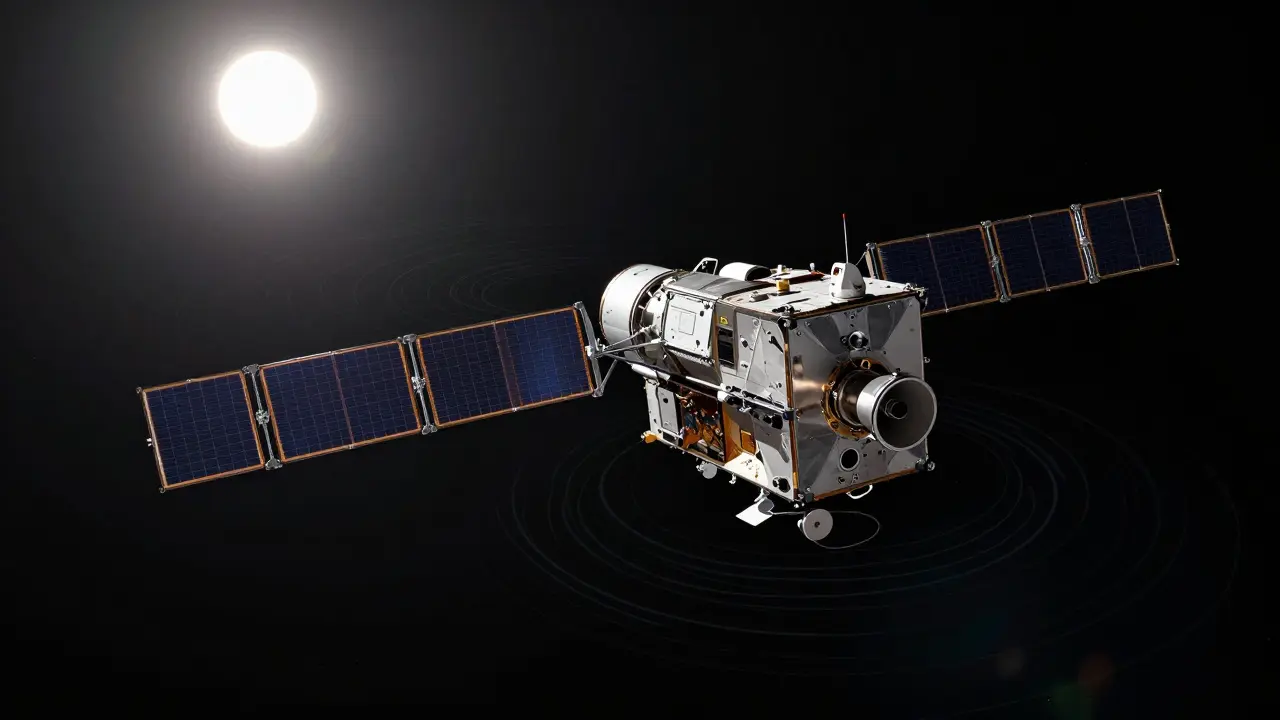
Spaceborne Instruments: Using Spin and Light
In the realm of space science, which relies on precise instrumentation to study celestial bodies and Earth's environment, two dominant strategies emerge: exploiting spacecraft dynamics and using onboard reference sources.
Magnetometers on Spinning Spacecraft
Magnetometers measure magnetic fields, but they often have inherent offsets and scale factor errors. The Imperial College London’s Space Magnetometer Laboratory, a research group specializing in space physics instrumentation, has developed techniques specifically for spinning spacecraft.
Here is how it works: As the spacecraft spins, the true ambient magnetic field vector traces a sinusoid relative to the sensor frame. By analyzing this rotation, algorithms can separate the steady external field from the instrument's internal biases. The mean and amplitude of the signal allow engineers to estimate offsets and scale factors in flight. This method requires no extra hardware, just smart math applied to the continuous data stream. It is particularly valuable for missions lasting decades, where ground-based recalibration is impossible.
Radiometric Instruments and Internal References
For instruments measuring light, such as those on the SORCE mission, which monitors solar irradiance to understand its impact on Earth's climate, internal optical paths are key. The Solar Irradiance Monitor (SIM) uses a mirror-rotator system. It measures light intensity before and after it passes through a prism. By taking the ratio of these two measurements, the system tracks its own throughput. If the detector degrades due to contamination or radiation, the ratio changes. This allows the team to quantify the degradation daily, ensuring the final solar data remains accurate throughout the mission's life.
For high-energy polarimetry, researchers use tools like GEANT4, a simulation toolkit for modeling particle interactions with matter. This software helps design onboard radioactive calibration sources. These sources provide a known signal inside the detector, allowing teams to verify performance without relying on external stars or planets.
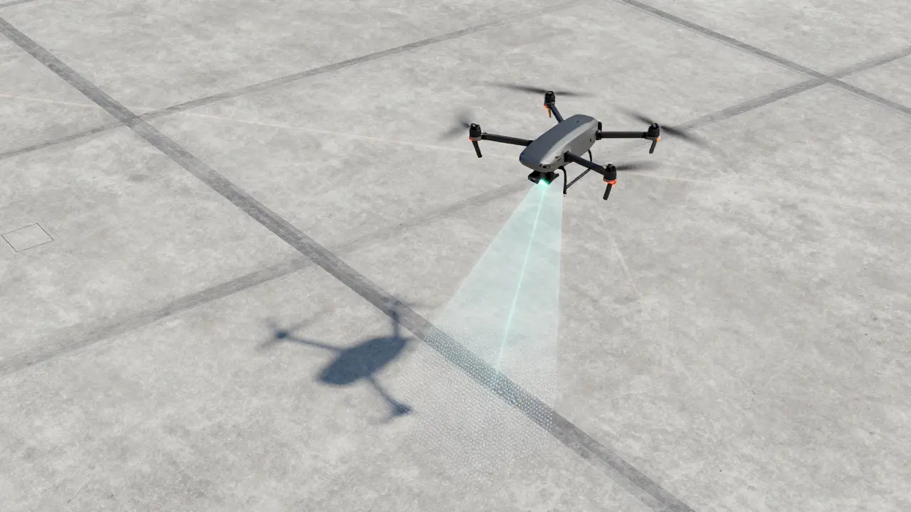
Airborne Systems: UAVs and LiDAR Calibration Flights
While satellites spin, drones fly. For UAV mapping, which uses unmanned aerial vehicles to capture geospatial data, precision depends on the alignment between the LiDAR sensor, the Inertial Measurement Unit (IMU), and the GNSS receiver. This alignment is called boresight. If it is off by even a fraction of a degree, buildings in your map might appear tilted or shifted.
Unlike space, you can land a drone. However, landing does not fix the dynamic errors that occur during flight. Therefore, professional workflows include dedicated "calibration flights" before major surveys.
The Phoenix LiDAR Strategy
Phoenix LiDAR Systems, a provider of airborne LiDAR solutions for surveying and mapping, outlines a rigorous process for this. Their strategy relies on geometric diversity. You cannot calibrate a sensor by flying straight lines forever. You need intersections.
The recommended pattern involves at least two sets of opposing flight lines intersecting perpendicularly. For best results, four sets are better, flown at different altitudes (e.g., 100 m and 140 m above ground level). The spacing between lines should be around 20 meters to ensure sufficient overlap. This overlap allows software to compare points from different angles. If the boresight is wrong, the overlapping strips will not match up perfectly. The algorithm minimizes these discrepancies to calculate the correct alignment.
The site matters too. You want hard surfaces-concrete roads, pitched roofs, street intersections. Avoid trees. Vegetation moves and bends, introducing noise that confuses the planar fitting algorithms used for calibration.
Dynamic Maneuvers for IMUs
LiDAR is only half the equation. The IMU tells the system which way the drone is pointing. To calibrate the IMU gyros and accelerometers, you must excite all axes. Phoenix LiDAR recommends specific maneuvers:
- Static alignment: Keep the system static for 3-10 minutes after power-on.
- Straight flight: Fly forward at minimum 5 m/s for 100 meters.
- Figure-eights: Perform at least three figure-eight patterns. This twists the aircraft, helping the system estimate gyro biases and scale factors accurately.
DJI takes a similar approach with their Matrice 300 RTK. Their "calibration flight" mode adds acceleration and deceleration phases at route start, end, and turning points. These dynamic changes enrich the velocity profile data, helping the control system model platform behavior more precisely for subsequent automated flights.
Algorithmic Estimation and Data Processing
Recalibration is not magic; it is mathematics. In both space and air, the raw data feeds into algorithms that solve for unknown variables.
For magnetometers, this is a regression problem. The algorithm fits the measured field over many spins to a known global magnetic field model (like IGRF). The difference reveals the sensor's offset and gain errors. For LiDAR, optimization routines minimize the elevation differences between overlapping strips. These algorithms run on the ground after the flight, but the principles apply to onboard processing too.
Cross-calibration is another powerful tool. If your satellite has two identical instruments pointing in slightly different directions, you can compare them. If one sees a star brighter than the other, you know one is degrading faster. This redundancy is critical for missions where failure is not an option.
| Domain | Primary Method | Key Hardware/Tool | Main Benefit |
|---|---|---|---|
| Space Magnetometry | Spin-based analysis | Spacecraft attitude data | No extra hardware needed |
| Solar Radiometry | Internal mirror-prism ratio | Mirror rotator system | Tracks throughput degradation |
| UAV LiDAR Mapping | Overlapping flight lines | High-res GNSS reference station | Corrects boresight alignment |
| Fixed-Wing Autopilot | Trim adjustment via logs | ArduPilot FBWA mode | Tunes control response dynamically |

Constraints and Pitfalls to Avoid
In-flight recalibration is powerful, but it has limits. Understanding these constraints prevents costly mistakes.
Trajectory Accuracy is King: For LiDAR, you cannot correct sensor misalignment if your position data is wrong. Phoenix LiDAR emphasizes using a GNSS reference station recording at 1 Hz with multiple constellations (GPS, GLONASS, Galileo, BeiDou). If the trajectory solution is poor, the calibration algorithm will produce false boresight values. Always invest in high-quality ground truth data.
Environmental Control: You cannot force a satellite to fly over a perfect concrete intersection. Space instruments must deal with whatever background radiation or thermal conditions exist. This is why internal references (like SORCE’s mirror system) are preferred-they are independent of the external environment.
Hardware Dependencies: Changing camera lenses or focus settings after a calibration flight invalidates the entire dataset. Ensure all optical components are locked down before the first calibration maneuver. Similarly, for Velodyne LiDAR sensors, setting the return mode to "dual return" during calibration affects how point clouds are generated, so consistency is key.
Future Directions: Model-Driven Design
The trend is moving toward simulation-driven calibration. Instead of guessing what calibration source strength you need, teams use tools like GEANT4 to simulate millions of particle interactions before launch. This optimizes the trade-off between calibration accuracy, exposure time, and resource usage. Future systems will likely integrate more automated, closed-loop calibration, where the instrument detects drift and automatically triggers a correction maneuver or updates its internal lookup tables without human intervention.
As missions get longer and regulatory demands for traceable accuracy increase, in-flight recalibration shifts from an occasional check to a continuous, integral part of mission design. It is the difference between a dataset that ages gracefully and one that becomes obsolete.
What is the primary purpose of in-flight recalibration?
The primary purpose is to maintain measurement accuracy over time by correcting for sensor drift, thermal changes, radiation damage, and mechanical misalignment that occur after launch or takeoff. It ensures that long-duration data remains scientifically or operationally trustworthy.
How do spinning spacecraft calibrate magnetometers?
They exploit the spacecraft's rotation. As the craft spins, the ambient magnetic field creates a sinusoidal signal relative to the sensor. Algorithms analyze the mean and amplitude of this signal to estimate and correct for sensor offsets, scale factors, and alignment errors without needing external references.
Why are perpendicular flight lines important for LiDAR calibration?
Perpendicular flight lines create overlapping data strips from different angles. This geometric diversity allows optimization algorithms to detect and minimize discrepancies caused by boresight misalignment between the LiDAR, IMU, and GNSS, leading to a more accurate calibration solution.
What role does GEANT4 play in calibration strategies?
GEANT4 is a simulation toolkit used to model particle interactions. In calibration, it helps designers optimize onboard radioactive sources for polarimetric detectors, ensuring they provide sufficient calibration statistics without saturating the detector, before the mission even launches.
Can in-flight recalibration replace ground calibration?
No, it complements it. Ground calibration establishes the baseline accuracy in a controlled environment. In-flight recalibration tracks deviations from that baseline caused by operational stresses. Both are necessary for high-integrity long-mission data.