
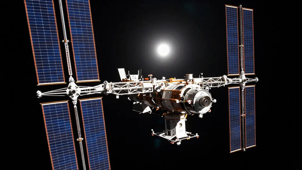
Imagine trying to push a heavy shopping cart across a smooth floor. If you use a strong chemical rocket, it's like giving the cart one massive shove. It moves fast, but you need a lot of fuel to do it. Electric propulsion is different. It's like using a small, steady fan attached to the cart. The push is tiny-barely noticeable at first-but if you keep it running for months or years, the cart goes incredibly far. The catch? That fan needs electricity. A lot of it. For long-duration space missions, determining how much electric propulsion power you need, and then figuring out exactly how big your solar panels and batteries must be to supply it, is one of the most critical engineering challenges in aerospace design.
This isn't just about plugging in numbers; it's about balancing mass, efficiency, and mission duration. A single kilowatt of continuous power in space can mean the difference between reaching an asteroid and falling short. Let's break down how engineers calculate these requirements, from the physics of thrust to the square meters of silicon needed to keep a spacecraft alive.
Understanding the Physics: Thrust, Power, and Efficiency
To size your power system, you first need to understand what the thruster actually demands. Electric thrusters, such as Hall-effect thrusters or ion engines, work by accelerating ions (charged particles) to high speeds. The key relationship here involves three variables: thrust force ($F$), exhaust velocity ($v_e$), and electrical efficiency ($\eta$).
The formula for electrical power ($P$) required is roughly: $$ P = \frac{F \cdot v_e}{2 \cdot \eta} $$ Here’s why this matters practically. High specific impulse ($I_{sp}$)-which translates to high exhaust velocity-is the main advantage of electric propulsion. It saves propellant mass. But high velocity requires significantly more energy per unit of thrust compared to chemical rockets.
- Low-Power Regime: Small satellites often use thrusters operating between 50 W and 600 W. These are sufficient for orbit adjustments or station-keeping.
- Medium-Power Regime: Missions like NASA's Dawn spacecraft used thrusters in the 0.5 kW to 2.3 kW range. This allowed them to visit multiple asteroids over several years.
- High-Power Regime: Flagship deep-space missions may require 10 kW to over 100 kW. For example, producing just 10 Newtons of thrust (roughly the weight of a 1 kg object on Earth) at a high specific impulse of 3000 seconds with 50% efficiency requires approximately 300 kW of electrical power.
This jump in power demand is why solar array sizing becomes so complex. You aren't just powering lights and computers; you're powering a continuous engine that runs for years.
Solar Array Sizing: From Watts to Square Meters
Once you know the power requirement, the next step is converting watts into physical area. This process involves several layers of inefficiency that must be accounted for. You can't just divide the required power by the sun's intensity; you have to factor in degradation, angle, and losses.
The standard formula for calculating solar array area ($A$) is: $$ A = \frac{P_{EOL}}{S \cdot \cos(\theta) \cdot \eta_{cell} \cdot \eta_{EOL} \cdot \eta_{harness}} $$ Let's define the variables in this equation, as they are the levers engineers pull during design:
- $P_{EOL}$ (End-of-Life Power): The power the array must deliver at the end of the mission, not the beginning. Solar cells degrade over time due to radiation and atomic oxygen erosion.
- $S$ (Solar Flux): At 1 AU (Earth's distance from the Sun), this is approximately 1361 W/m². As you move further from the Sun, this drops by the square of the distance. At Mars (1.5 AU), it's only about 610 W/m².
- $\cos(\theta)$ (Incidence Angle): How directly the sunlight hits the panel. Panels are usually pointed at the Sun, so this is close to 1, but attitude control limits can reduce it.
- $\eta_{cell}$ (Cell Efficiency): Modern multi-junction cells can reach 30-35% efficiency in space. Older silicon cells were around 15-20%.
- $\eta_{EOL}$ (Degradation Factor): Engineers typically assume a 25-33% loss over the mission lifetime. So, if you need 100 kW at the end, you might need to start with 140 kW.
- $\eta_{harness}$ (Harness Efficiency): Energy lost in wiring and distribution systems. This is typically 80-90% efficient.
Consider a concrete example. Suppose a mission requires 1 kW of continuous power at the end of life. Using conservative estimates (30% cell efficiency, 70% EOL retention, 85% harness efficiency) at 1 AU: $$ A = \frac{1000}{1361 \cdot 1 \cdot 0.30 \cdot 0.70 \cdot 0.85} \approx 4.3 \text{ m}^2 $$ Now, scale that up. For a 300 kW class mission, assuming similar efficiencies, you would need roughly 1,300 to 1,500 square meters of solar array area. To put that in perspective, that's larger than two football fields. This massive area drives the structural design of the entire spacecraft, requiring robust deployable wings and precise attitude control to keep those large surfaces pointed correctly.
Battery Sizing: Handling the Night Shift
Solar arrays only work when the spacecraft is in sunlight. In low Earth orbit (LEO), spacecraft spend significant time in eclipse. Even in deep space, if a spacecraft orbits a planet, it will encounter eclipses. During these periods, the thrusters might be turned off to save power, but the spacecraft bus (computers, heaters, communications) still needs energy. This is where batteries come in.
Battery sizing is driven by the "charge balance" equation. The energy stored in the battery must cover the loads during eclipse, plus any recharge cycles needed to maintain battery health. The basic logic follows these steps:
- Determine Eclipse Duration: How long is the spacecraft in shadow? For LEO, this is about 35 minutes per 90-minute orbit. For deep space planetary orbits, it varies widely.
- Calculate Eclipse Load: What is the minimum power draw? If the thruster is off, this might be 200-500 W for housekeeping. If the thruster stays on (rare for high-power EP due to battery limitations), add the thruster power.
- Select Depth of Discharge (DOD): Lithium-ion batteries shouldn't be drained completely. A typical DOD limit is 40-80%, depending on the desired cycle life. Lower DOD means longer battery life but heavier packs.
- Apply Specific Energy: Current space-grade lithium-ion batteries offer around 150-200 Wh/kg. Higher energy density reduces mass.
For a small satellite with a 1 kW EP system, the battery might only need to support 500 W of housekeeping loads for 30 minutes. That's $500 \text{ W} \times 0.5 \text{ h} = 250 \text{ Wh}$. With a 50% DOD, you'd need a 500 Wh battery pack. At 150 Wh/kg, that's roughly 3.3 kg of batteries. Not huge, but every kilogram counts.
However, for high-power SEP missions, the dynamic changes. If the thruster operates continuously, the solar array must be sized not just for the average power, but to recharge the battery sufficiently during sunlight while also powering the thruster. This creates a coupled design problem: bigger arrays allow smaller batteries, and vice versa. Engineers iterate on this trade-off until the total mass of the EPS (Electrical Power Subsystem) is minimized.
Case Studies: Real-World Applications
Looking at actual missions helps ground these calculations in reality.
NASA's Dawn Mission
Dawn used a gridded ion thruster (NSTAR) that operated between 0.5 kW and 2.3 kW. Its solar arrays were relatively small, providing up to 2.4 kW at beginning-of-life. Because Dawn spent years traveling to Vesta and Ceres, its arrays degraded significantly. By the end of the mission, the available power was much lower, forcing the mission planners to limit thruster operation time. This highlighted the importance of accurate EOL degradation modeling.
Lunar Gateway Power and Propulsion Element (PPE)
The upcoming Gateway station will feature the PPE, which includes two AEPS Hall thrusters capable of delivering up to 60 kW of combined power. This is a massive leap from previous missions. To support this, the PPE features large, flexible solar array wings. The design targets a specific power (power-to-mass ratio) of over 100 W/kg for the array system. This means for every kilogram of array structure and cells, you get 100 watts of power. Achieving this requires advanced materials and deployment mechanisms that can handle the stresses of unfurling hundreds of square meters in vacuum.
Small Satellite Constellations
For CubeSats and small sats, the approach is simpler but tighter. A 1U CubeSat might use a 10 W EP thruster. The solar array might be just a few square feet. The battery is a small Li-ion pack. Here, the challenge isn't the sheer size, but the integration. Fitting the array, battery, and power processing unit into a tiny volume while maintaining thermal stability is a distinct engineering puzzle.
Key Trade-offs and Design Considerations
When sizing these systems, engineers face several competing constraints:
- Mass vs. Performance: Larger arrays provide more power but add mass and drag (in LEO). Heavier batteries store more energy but increase launch costs. The goal is to find the sweet spot where total system mass is lowest.
- Voltage Levels: High-power EP systems often operate at high voltages (500-600 V) to reduce current and thus resistive losses in the wiring. However, high voltage requires better insulation and safety margins, adding complexity.
- Thermal Management: Solar arrays heat up in sunlight and cool down in shadow. Large arrays for high-power EP generate significant waste heat in the power processing units. Managing this heat without overheating components is critical for longevity.
- Mission Profile: A mission to the outer solar system (e.g., Jupiter) has less solar flux than one near Earth. This means arrays must be exponentially larger to produce the same power. For missions beyond Mars, nuclear electric propulsion is often considered because solar arrays become impractically large.
Future Trends: Scaling Up
The trend in electric propulsion is clearly toward higher power. NASA and industry partners are developing arrays with specific powers exceeding 200 W/kg. New materials, such as carbon nanotubes and advanced composites, are being tested to make arrays lighter and stiffer. Additionally, improvements in battery technology, including solid-state batteries, promise higher energy densities, which could reduce the mass penalty of storing energy for eclipse periods.
As we look toward crewed missions to Mars and robotic exploration of the outer planets, the ability to efficiently size solar arrays and batteries for high-power electric propulsion will be a defining factor in mission success. It’s a discipline that blends physics, materials science, and systems engineering, ensuring that every watt generated is used effectively to propel humanity further into the cosmos.
Why do electric propulsion systems need larger solar arrays than chemical rockets?
Electric propulsion trades high thrust for high efficiency. While chemical rockets burn fuel quickly to produce massive force, electric thrusters use electrical energy to accelerate ions slowly but continuously. This allows them to use far less propellant, but they require a constant supply of electrical power. Since solar arrays are the primary source of this power in inner solar system missions, their size must be scaled to meet these continuous, high-duty-cycle power demands, often resulting in arrays that are tens or even hundreds of times larger than those on chemical-only spacecraft.
How does distance from the Sun affect solar array sizing?
Solar flux decreases with the square of the distance from the Sun. At 1 AU (Earth's orbit), the solar constant is about 1361 W/m². At 2 AU (Mars' orbit), it drops to about 340 W/m². This means a spacecraft at Mars needs four times the array area to generate the same amount of power as one at Earth. For missions to the outer planets, solar arrays become prohibitively large, which is why nuclear power sources are often preferred for those destinations.
What is the role of batteries in electric propulsion missions?
Batteries store energy to power the spacecraft during eclipses or when the solar array is not optimally aligned. In many EP missions, the thrusters are turned off during eclipse to conserve battery charge, leaving only essential housekeeping systems running. However, the solar array must be sized large enough to recharge the batteries fully during sunlight periods while also supplying power to the thrusters. Battery capacity is determined by the duration of the eclipse, the load during that period, and the acceptable depth of discharge to ensure battery longevity.
What is 'specific power' in the context of solar arrays?
Specific power is the ratio of electrical power output to the mass of the solar array system, measured in watts per kilogram (W/kg). It is a critical metric for spacecraft designers because every kilogram of mass adds cost and complexity. Higher specific power means you can generate more electricity with less weight. Current state-of-the-art flexible arrays achieve around 100-150 W/kg, while future goals aim for 200-250 W/kg to enable more ambitious high-power missions.
Can electric thrusters run during eclipse?
It depends on the mission profile and battery capacity. For small satellites with low-power thrusters, it might be feasible to keep the thruster running during short eclipses if the battery is large enough. However, for high-power SEP missions, the power draw is too high for batteries to sustain for long periods. Therefore, thrusters are typically powered down during eclipse, and the spacecraft relies on momentum or other methods for attitude control until sunlight returns. This duty cycle must be factored into the overall mission delta-v calculation.