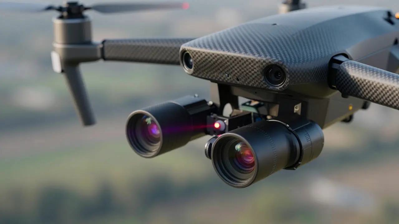
Imagine pointing two high-resolution cameras at the same target from a drone flying at 100 meters altitude. One camera sees infrared heat signatures; the other captures visible light details. If their optical axes are even slightly misaligned, the fused image looks like a blurry ghost story rather than a clear picture. This is where boresight alignment becomes critical. It is not just about making sensors point in the same direction-it is about ensuring that every pixel, laser pulse, and data point from multiple instruments corresponds perfectly in space and time.
In modern remote sensing, defense systems, and scientific observation, single-sensor platforms are becoming rare. Instead, we see complex multi-instrument payloads consisting of combinations of LiDAR, multispectral cameras, thermal imagers, and inertial navigation units mounted on a common platform. When these instruments do not share a precise reference frame, the resulting data is useless for tasks like change detection, precision targeting, or 3D mapping. Boresight alignment fixes the physical angular errors, while co-registration is the software process that corrects residual geometric mismatches between images or point clouds. Together, they form the backbone of accurate sensor fusion.
The Core Problem: Angular Misalignment
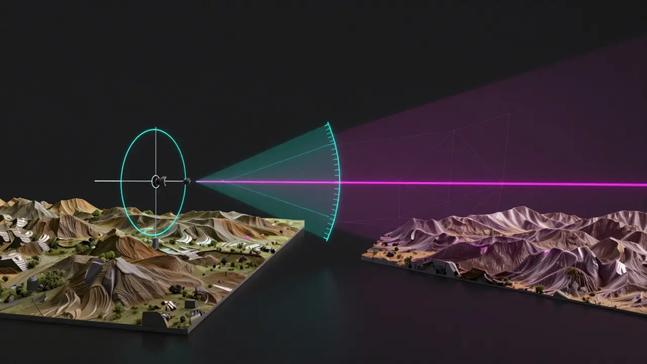
At its simplest, boresight error is the angle between the optical axis of a sensor and the mechanical axis of its mount. In a perfect world, these would be identical. In reality, manufacturing tolerances, thermal expansion, and vibration during flight introduce tiny deviations. For a UAV LiDAR system, this might mean the scanning reference coordinate system is tilted by a fraction of a degree relative to the onboard GPS/INS unit. This seems small until you realize that a 100-microradian error at a 10-kilometer range translates to a lateral miss of one meter. In precision targeting or ice-sheet topography measurement, that margin is unacceptable.
The U.S. Navy’s recent SBIR topic N241-026 highlights this challenge explicitly, demanding automated in-situ alignment capabilities that achieve better than 100 microradians (approximately 20.6 arcseconds). Why such tight tolerances? Because modern multi-spectral imaging sensors and lasers operate with narrow fields of view. If the director line-of-sight does not coincide with the imaging sensor’s center within this tolerance, the system cannot accurately fuse data from different spectral bands. The goal is to ensure that when a laser hits a specific point on the ground, the camera looking at that same point sees exactly what the laser measured, without any spatial offset.
Hardware Solutions: Mechanical and Optical Adjustments
Historically, engineers have relied on physical adjustments to fix boresight errors. NASA’s Geoscience Laser Altimeter System (GLAS) provides a classic example. During the ICESat mission timeframe (2003-2009), scientists needed to align transmit and receive laser paths to within 30 arcseconds to ensure full science data quality. They developed a Boresight Adjustment Mechanism (BAM) capable of steering three independent laser beams by less than 1 arcsecond over a ±300 arcsecond mechanical range. This level of precision allowed the instrument to maintain at least 50% full-width-at-half-maximum response even at 42 arcseconds of misalignment.
However, adding moving parts to spaceborne instruments introduces mass, complexity, and risk. In some cases, observatory-level testing showed that existing instrument resources provided sufficient margin, leading programs to skip integrating heavy BAM hardware. For terrestrial and airborne applications, simpler optical techniques often suffice. A 1999 patent described an elegant method using a pinhole target aperture. By burning a hole in a target and illuminating it from behind with visible or infrared light, operators could adjust day and night scopes so their optical axes coincided with the laser beam path. This multi-spectral alignment required no permanent hardware additions to the sensors themselves.
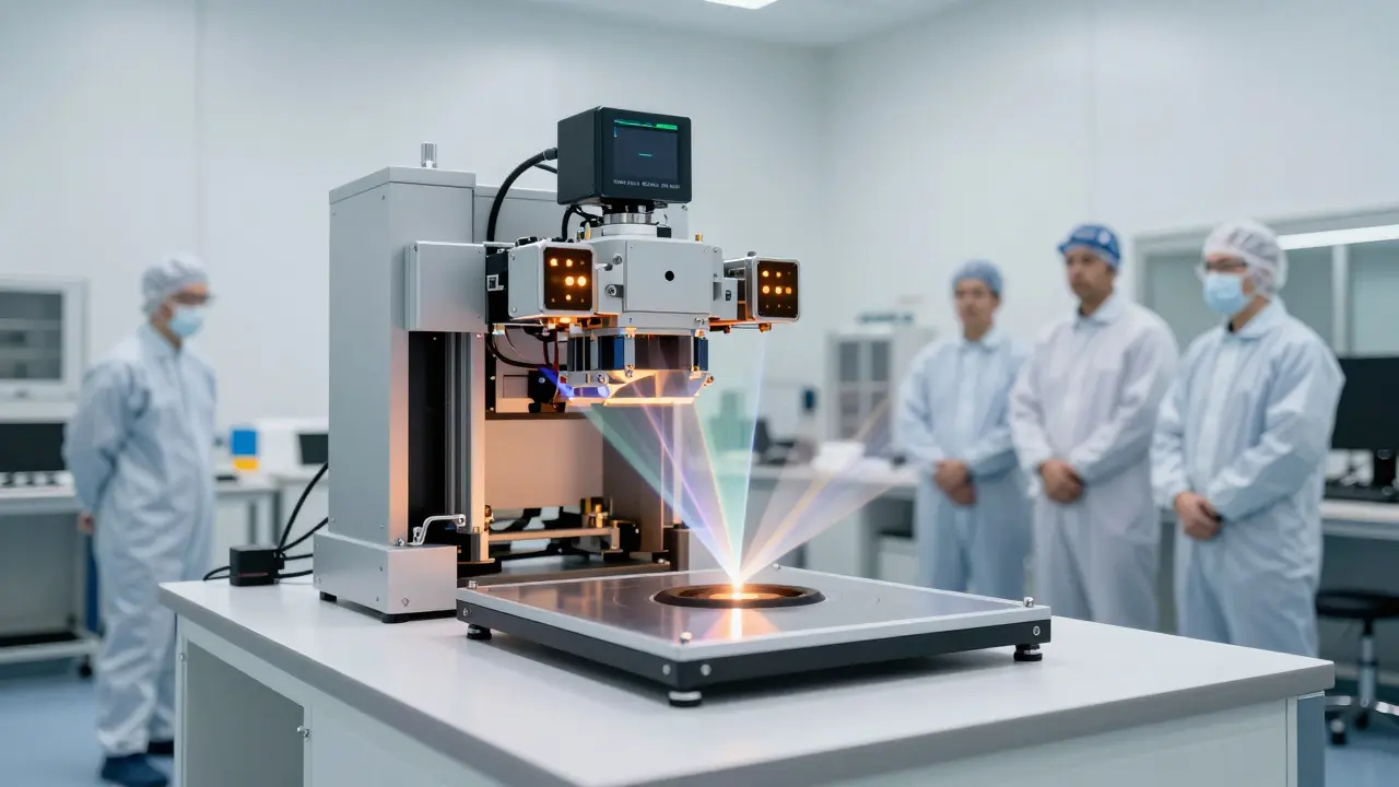
More recently, companies like Santa Barbara Infrared have introduced commercial modules that automate this process. Their Boresight Alignment Module combines a shortwave infrared camera with an optical target wheel inside a collimator. Using autocollimation, the system transfers the collimator’s line of sight to the camera, establishing a precise boresight reference. Integrated with software like IRWindows 5, this setup can automatically measure and adjust alignment between multiple imaging sensors and laser transmitters operating between 850 nm and 2000 nm wavelengths. What used to take hours of manual tweaking now happens in minutes, reducing human error and increasing repeatability.
| Method | Accuracy Range | Typical Application | Key Advantage |
|---|---|---|---|
| Mechanical BAM (e.g., GLAS) | <1 arcsecond | Spaceborne Laser Altimeters | Sub-arcsecond steering capability |
| Optical Pinhole/Illumination | ~18 arcseconds | Multi-spectral Sensors | No permanent hardware mods |
| Laser Tracker (LTAS) | High Precision | Aircraft Avionics (F-16) | Common reference frame for all instruments |
| Automated SWIR Modules | Sub-pixel / ~100 µrad | Defense & Surveillance | Fast, automated, wide wavelength coverage |
Software Co-Registration: Fixing Residual Errors
Even with perfect hardware alignment, environmental factors like temperature changes, platform flexure, and atmospheric distortion can introduce new misalignments during operation. This is where software-based image co-registration steps in to correct residual geometric errors after data acquisition. Unlike boresight alignment, which adjusts physical components, co-registration mathematically shifts and warps pixels so that every pixel from one sensor corresponds spatially to pixels in a reference sensor.
Tools like GeoWombat integrate libraries such as AROSICS to perform this task efficiently. These systems use xarray DataArray structures as input and apply automated shifting algorithms to bring misaligned pixels into exact spatial correspondence. This approach is particularly valuable for time-series analysis, where you need to compare images taken months apart by the same satellite. Without co-registration, slight orbital drifts or sensor degradation would make change detection impossible.
For multi-camera miniature systems, the challenge is even greater. A 2019 study published in the ISPRS Archives demonstrated that robust co-registration methods could accurately fuse multispectral images from separate cameras, remaining invariant to relative image shifts and rotations within specified ranges. This means that even if the mechanical mounting of the cameras isn’t perfect, the software can compensate for typical misalignments on the order of several pixels or a few degrees in orientation. The result is a seamless mosaic that behaves as if it came from a single, perfectly aligned sensor.
LiDAR Calibration: The Largest Systematic Error
In UAV LiDAR deployments, boresight error is often cited as the largest single systematic error source. When a LiDAR sensor scans the ground, it relies on precise synchronization with the onboard GPS and Inertial Navigation System (INS). If the scanning reference coordinate system is misaligned with the INS coordinate system, the resulting point cloud will show visible strip misalignments. Adjacent swaths of data won’t overlap cleanly; instead, you’ll see offsets that look like cracks in a pavement.
Geodetics’ workflow for calibrating Geo-MMS LiDAR and Point&Pixel payloads illustrates how this is handled in practice. First, the payload is physically mounted on the drone. Engineers accept that human mounting cannot guarantee perfect parallelism between scanning and inertial axes. Next, they conduct boresight calibration flights over flat terrain with overlapping strips. By analyzing the raw point cloud, they identify offsets between adjacent strips. Software then computes the necessary boresight angles-pitch, roll, and yaw corrections-and applies them to remove the systematic error. This process often requires several flights and days of data processing to refine the calibration to sub-centimeter accuracy.
This iterative approach highlights a key difference between static laboratory alignment and dynamic field calibration. While lab tests can achieve theoretical perfection, real-world conditions demand flexible, data-driven corrections. As UAV constellations grow, automating this calibration loop becomes essential. Future systems will likely rely on tightly coupled hardware and software loops that continuously monitor and adjust boresight parameters in real-time, maintaining co-registration as platforms age and environmental conditions change.
Future Trends: Automation and Integration
The industry is moving toward higher levels of automation. The U.S. Navy’s call for automated in-situ boresight alignment reflects a broader trend across defense and commercial sectors. Current solutions often require specialized metrology equipment, trained operators, and controlled environments. For example, ATT Metrology’s Laser Tracker Alignment System (LTAS) delivers high-precision alignment for F-16 aircraft by measuring positions of multiple instruments relative to a reference tracker. While highly effective, this method is limited to maintenance phases rather than operational use.
Looking ahead, we expect to see more integrated solutions that combine optical targets, video camera systems, and advanced algorithms into compact modules. Santa Barbara Infrared’s recent products suggest a shift toward user-friendly workflows that reduce alignment time from hours to minutes. Similarly, research into robust fine registration for multisensor remote sensing images indicates that future payloads will rely increasingly on software co-registration to complement hardware boresight alignment. As small satellites and micro-UAVs proliferate, the ability to automatically compensate for imperfect mechanical alignments will become a standard feature rather than a luxury.
Ultimately, successful multi-instrument payloads depend on a holistic approach. You cannot rely solely on hardware precision or software correction. The most effective systems combine rigorous initial boresight alignment with continuous software co-registration, ensuring that every data point-from laser pulses to thermal pixels-contributes to a coherent, accurate picture of the world below.
What is the difference between boresight alignment and co-registration?
Boresight alignment is a hardware or pre-flight calibration process that physically adjusts the optical axes of sensors to match a common reference frame, typically achieving angular tolerances of 1 arcsecond to 100 microradians. Co-registration is a post-processing software technique that corrects residual geometric mismatches between images or point clouds by shifting and warping pixels to ensure spatial correspondence.
Why is boresight error considered the largest systematic error in UAV LiDAR?
In UAV LiDAR, boresight error represents the angular misalignment between the LiDAR scanner’s coordinate system and the onboard GPS/INS unit. Even minute misalignments cause visible offsets between adjacent data strips in the point cloud, degrading the accuracy of 3D models. Since LiDAR relies on precise synchronization of position, orientation, and scan angle, any deviation directly impacts the final geospatial accuracy.
How accurate do modern boresight alignment systems need to be?
Requirements vary by application but generally fall between 1 arcsecond and 100 microradians. For example, the U.S. Navy demands better than 100 microradians for targeting systems, while spaceborne laser altimeters like NASA’s GLAS required alignment better than 30 arcseconds between transmit and receive paths to ensure valid science data.
Can software co-registration replace physical boresight alignment?
No, software co-registration cannot fully replace physical boresight alignment. While software can correct residual geometric errors and pixel-level misalignments, it cannot fix physical issues like vignetting, reduced optical throughput, or severe pointing errors that prevent sensors from viewing the same target area. Hardware alignment ensures the sensors are looking at the right place; software refines the data fusion.
What tools are commonly used for automated co-registration?
Popular tools include GeoWombat with the AROSICS library for image-based co-registration, and various point cloud processing suites for LiDAR data. These systems use algorithms for feature matching, local geometric corrections, and automated shifting to achieve sub-pixel accuracy, enabling seamless fusion of data from multiple sensors or time series.