

Imagine launching a car-sized spacecraft into orbit, only to find its power source stuck like a broken umbrella. This isn't a hypothetical scenario; it's the nightmare that plagued NASA's Lucy mission in 2021. One of its massive solar arrays refused to fully unfurl due to a tangled lanyard, threatening the entire mission to the asteroid belt. The culprit wasn't exotic physics or alien interference-it was a mechanical failure in the array deployment mechanism. These devices are the unsung heroes of space power, responsible for transforming compact, launch-stowed panels into sprawling energy harvesters once in orbit.
Space is hostile to moving parts. There’s no gravity to help things settle, extreme temperature swings that make metal brittle or soft, and vacuum conditions that can cause lubricants to evaporate or metals to weld themselves together. Yet, we need huge surface areas to collect sunlight. The solution lies in three critical components: hinges that rotate, booms that extend, and latches that lock everything in place. Understanding how these work-and why they fail-is essential for anyone interested in modern satellite engineering.
The Role of Hinges in Solar Array Deployment
A hinge provides the rotational freedom needed to unfold solar panels from their stowed position. In the early days of spaceflight, engineers relied on simple passive systems. Think of a spring-loaded door closer: you store energy during launch, and when released, that energy drives the motion. Passive hinges use torsion springs, tape springs, or superelastic shape-memory alloys (SMAs) to deploy arrays without needing continuous electrical power. This approach is lightweight and reliable because there are fewer electronics to fail.
However, passive systems have limits. They can’t stop mid-deployment, reverse direction if something goes wrong, or track the Sun precisely. That’s where active hinges come in. Also known as Solar Array Drive Assemblies (SADAs), these units include motors, gearboxes, and encoders. A typical commercial SADA, such as those made by Comat Space or Moog, weighs between 0.5 kg and 5 kg and consumes 4-15 watts of power. While heavier and more complex, active hinges offer control. They allow the array to rotate slowly to avoid shock loads, retract if necessary, and maintain precise orientation toward the Sun for maximum power generation.
Consider the ALBus CubeSat mechanism, which used SMA-driven hinges. It demonstrated how smart materials could replace traditional springs. When heated by an electric current, the SMA elements changed shape, pushing the hinge open. But even here, engineers added a mechanical latch as a failsafe. Why? Because cold temperatures in space can reduce the stiffness of some elastic materials, potentially causing the array to fold back if not locked. This highlights a core principle: redundancy is king.
Booms: Extending Reach Without Adding Mass
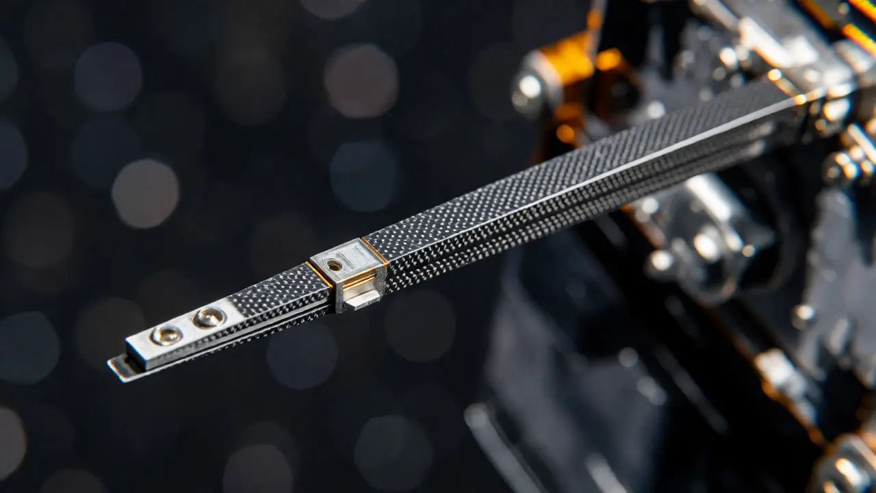
Not all solar arrays attach directly to the spacecraft body. Sometimes, you need distance-to keep panels away from antenna shadows, thermal radiators, or simply to get more area within the rocket fairing’s tight confines. Enter the boom. A deployable boom is a cantilever arm that extends outward after launch, carrying instruments or solar cells at its tip. Unlike rigid structures that might fit inside a small satellite, booms pack down tightly and then expand dramatically.
Modern booms often use composite materials rather than aluminum or steel. For instance, NASA Langley’s Deployable Composite Boom technology offers high stiffness while weighing 25% less than metallic equivalents. The Advanced Composite Solar Sail System (ACS3), launched in April 2024, proved this concept by extending a 7-meter composite boom to over 16 meters in space. Such scaling is impressive but tricky. Long, thin structures are flexible. They vibrate easily, which can confuse sensors or damage delicate connections. Engineers must balance flexibility for packing with rigidity for operation.
There are several types of booms, each with trade-offs:
- Telescoping tubes: Like a TV antenna, sections slide out. Simple but prone to jamming if debris gets between segments.
- Coilable booms: Made of slotted metal strips that uncoil. Great for long spans but require careful tensioning to prevent buckling.
- Tape-spring booms: Use curved metal tapes that snap into a straight shape. Efficient packaging but sensitive to manufacturing tolerances.
- Roll-out composites: Thin sheets rolled up and extended via a motor or spring. Excellent for large-area applications like solar sails.
The choice depends on the mission. If you’re deploying a high-gain antenna far from the bus to reduce interference, a stiff telescoping boom might be best. If you’re unfurling a giant solar sail, a roll-out composite system makes sense. But remember: every extension point is a potential failure mode. If a boom doesn’t lock securely, it can wobble uncontrollably, draining power and confusing attitude control systems.
Latches and Releases: The Critical Locks
If hinges provide motion and booms provide reach, latches provide certainty. A deployed solar array must stay exactly where it’s supposed to, regardless of thermal expansion, vibration, or maneuvering forces. Without a positive mechanical lock, the array could drift, misaligning the solar cells or stressing cables.
The process involves two distinct phases: release and retention. First, the array must be held firmly during launch vibrations. Devices like frangibolts, burn wires, or pin pullers do this job. Once in orbit, a command triggers these restraints to break or withdraw, allowing deployment. After the array reaches its final position, a second set of latches engages. These aren’t just clips; they’re precision-engineered detents that click into place with audible or electrical confirmation.
Sensing is crucial here. How do operators know the latch engaged? Usually through microswitches, Hall effect sensors, or encoders. But sensors lie-or rather, they can be fooled. During a Magellan mission incident, a latch indication anomaly occurred because the microswitch stroke was marginal. In zero gravity, the hinge behaved differently than on Earth, leading to false readings. This underscores the importance of independent verification. Never rely solely on one sensor type.
Commercial examples illustrate the diversity of solutions. Arquimea’s HDRM uses spring-driven deployment with integrated sensors for start and completion detection. SpaceTech’s C-Blade design uses a tape spring to both drive and latch the hinge, preventing chaotic unfolding. Meanwhile, Sierra Space’s paraffin actuators use phase-change materials to generate force for releases. Each option trades off mass, power, complexity, and reliability.
| Component Type | Primary Function | Typical Mass Range | Power Consumption | Key Advantage | Major Risk |
|---|---|---|---|---|---|
| Passive Hinge (Spring/SMA) | Rotational deployment | < 1 kg | 0 W (passive) / Low (SMA heater) | Simplicity, low mass | Uncontrolled rate, no reversal |
| Active SADA | Controlled rotation/tracking | 0.5 - 5 kg | 4 - 15 W | Precision, reversibility | Motor/gearbox failure, higher cost |
| Composite Boom | Structural extension | Variable (lightweight) | N/A | High span-to-mass ratio | Buckling, dynamic instability |
| Frangibolt/Pin Puller | Launch restraint release | < 0.1 kg | 2 - 15 W (pulse) | Positive separation | Non-explosive actuation failure |
| Mechanical Latch | Deployed position retention | < 0.5 kg | N/A | Zero-power holding | Misalignment, thermal binding |

Why Do These Mechanisms Fail?
Mechanisms account for over 10% of reported small-satellite failures. That’s a staggering statistic given their apparent simplicity. So what goes wrong? Often, it’s not the big gears or motors, but the small details: friction, temperature, and alignment.
Take the Mars Global Surveyor incident. A solar panel failed to fully deploy and latch. Analysis revealed that a damper arm had jammed inside the hinge. The resulting stress fractured part of the yoke structure. Why did it jam? Possibly due to contamination, lubricant migration, or unexpected thermal contraction. In space, you can’t grease a bearing again if it dries out. You can’t tap a stuck part loose. Everything must work perfectly the first time.
Temperature plays a huge role. Materials expand and contract differently. A latch designed at room temperature might bind when cooled to -100°C in shadow. Or worse, it might become too loose, failing to hold under load. Friction also changes drastically in vacuum. Lubricants behave differently without air pressure, and cold welding can occur between clean metal surfaces. NASA Standard 5017B mandates rigorous testing under flight-like conditions to catch these issues early.
Harness management is another silent killer. Wires connecting the array to the bus must flex as the panel moves. If routed poorly, they can pinch, snag, or twist until they break. On the Lucy mission, a lanyard snarled on its spool prevented full deployment. It wasn’t a motor failure; it was a cable management issue. Ground tests showed that warming the spacecraft helped untangle it, highlighting how environmental factors influence mechanical performance.
Best Practices for Reliable Deployment
Given the risks, how do engineers ensure success? Simplicity is the first rule. If you don’t need a motor, don’t use one. Passive systems have fewer parts to break. But if you do use active systems, build in redundancy. The Landsat-D power hinge used mechanically and electrically redundant motors. If one failed, the other could take over. This philosophy extends to sensing: use multiple methods to confirm status.
Testing is non-negotiable. "Test as you fly" means subjecting hardware to actual launch vibrations, thermal cycles, and vacuum conditions. Subsystem-level tests aren’t enough; integration tests reveal interactions between harnesses, structures, and mechanisms. A hinge might work fine alone but fail when attached to a flexible panel that bends under load.
Design margins matter too. Don’t size your motor for exactly the torque needed. Add margin for friction spikes, aging, and unexpected loads. Similarly, choose materials compatible with space environments. Avoid dissimilar metals that corrode together. Use coatings to prevent cold welding. And always consider the worst-case scenario: what happens if the primary latch misses? Is there a secondary lock? Can the system tolerate partial deployment?
Looking ahead, trends favor lighter, smarter materials. Shape-memory alloys and paraffin actuators offer compact, low-power alternatives to traditional motors. Origami-inspired folding patterns allow larger arrays to fit in smaller volumes. As missions scale-from tiny CubeSats to giant deep-space probes-the demand for robust, scalable deployment mechanisms grows. We’re seeing more commercial suppliers entering the market, driving innovation in cost and performance. But despite technological advances, the fundamental challenge remains: making moving parts survive years in a harsh, unforgiving environment.
What is the main difference between passive and active deployment mechanisms?
Passive mechanisms use stored energy, like springs or shape-memory alloys, to deploy arrays without continuous power. They are simpler and lighter but offer less control. Active mechanisms use motors and gearboxes to drive deployment, allowing for controlled speed, reversal, and sun-tracking, but they add mass, complexity, and power requirements.
Why are latches so critical in solar array deployment?
Latches provide positive mechanical retention at the deployed position. Without them, thermal cycling, vibration, or maneuvering forces could cause the array to shift or refold, misaligning solar cells and stressing electrical connections. They ensure the array stays rigid and correctly oriented for optimal power generation.
How do booms differ from standard solar array hinges?
Hinges primarily provide rotational movement for folding/unfolding panels attached near the spacecraft body. Booms are structural members that extend linearly or radially to place arrays or instruments farther away from the bus. Booms address packaging constraints and interference issues but introduce challenges related to stiffness, dynamics, and long-span stability.
What caused the solar array issue on NASA's Lucy mission?
One of Lucy's solar arrays failed to fully unfurl and latch because a lanyard intended to pull the array open likely snarled on its spool. Repeated attempts using backup motors improved stability but didn't achieve full latching, forcing NASA to accept a partially deployed configuration to preserve mission safety.
Are composite booms better than metallic ones?
Composite booms typically offer higher stiffness-to-weight ratios and better thermal stability compared to metallic ones, often weighing 25% less. However, they can be more expensive and require careful design to handle dynamic loads and prevent buckling. The choice depends on specific mission requirements for mass, volume, and structural integrity.